カスタムBackendの作成とトランスパイル
# Added by doQumentation — required packages for this notebook
!pip install -q numpy qiskit rustworkx
# Don't use SVGs for this file because the images are too large,
# and the SVGs are much larger than their PNGs equivalents.
%config InlineBackend.figure_format='png'
```json

{/* cspell:ignore multichip interchip Lasciate ogne speranza voi ch'intrate */}
{/*
  DO NOT EDIT THIS CELL!!!
  This cell's content is generated automatically by a script. Anything you add
  here will be removed next time the notebook is run. To add new content, create
  a new cell before or after this one.
*/}

<details>
<summary><b>パッケージのバージョン</b></summary>

このページのコードは、以下の要件を使用して開発されました。
これらのバージョン以降を使用することを推奨します。
qiskit[all]~=2.4.0
</details>
{/* cspell:ignore LOCC */}

Qiskitのより強力な機能の一つは、独自のデバイス設定をサポートする能力です。Qiskitは使用する量子ハードウェアのプロバイダーに依存しないよう設計されており、プロバイダーは`BackendV2`オブジェクトを独自のデバイスプロパティに合わせて設定できます。このトピックでは、独自のBackendを設定し、それに対して量子回路をトランスパイルする方法を示します。

異なるジオメトリや基底ゲートを持つ独自の`BackendV2`オブジェクトを作成し、それらの設定を考慮して回路をトランスパイルできます。以下の例では、量子ビットの格子が分離したBackendを取り上げます。このBackendでは、エッジ部分とバルク内部で基底ゲートが異なります。

## Provider、BackendV2、Targetインターフェースの理解 \{#understand-the-provider-backendv2-and-target-interfaces}

始める前に、[`Provider`](../api/qiskit/providers)、[`BackendV2`](../api/qiskit/qiskit.providers.BackendV2)、および[`Target`](../api/qiskit/qiskit.transpiler.Target)オブジェクトの使用目的を理解しておくことが有益です。

- Qiskit SDKに統合したい量子デバイスやシミュレーターがある場合は、独自の`Provider`クラスを作成する必要があります。このクラスは単一の目的を持ちます:あなたが提供するBackendオブジェクトを取得することです。必要な認証情報や認証タスクはここで処理されます。インスタンス化されたプロバイダーオブジェクトは、Backendのリストを提供するとともに、Backendの取得やインスタンス化を行う機能も提供します。

- 次に、Backendクラスは、Qiskit SDKと回路を実行するハードウェアやシミュレーターとの間のインターフェースを提供します。トランスパイラーに対してBackendを記述するための必要な情報をすべて含んでおり、制約に従って回路を最適化できます。`BackendV2`は4つの主要な部分で構成されています:
  - [`Target`](../api/qiskit/qiskit.transpiler.Target)プロパティ:BackendConstraintの記述を含み、トランスパイラーに対してBackendのモデルを提供します
  - `max_circuits`プロパティ:1つのジョブでBackendが実行できる回路数の制限を定義します
  - ジョブの送信を受け付ける`run()`メソッド
  - ユーザーが設定可能なオプションとそのデフォルト値を定義する`_default_options`のセット

## カスタムBackendV2の作成 \{#create-a-custom-backendv2}

`BackendV2`オブジェクトは、プロバイダーが作成するすべてのBackendオブジェクト(`qiskit.providers`内、または[`qiskit_ibm_runtime.IBMBackend`](../api/qiskit-ibm-runtime/ibm-backend)などの別ライブラリ)に使用される抽象クラスです。前述の通り、これらのオブジェクトには[`Target`](https://docs.quantum.ibm.com/api/qiskit/qiskit.transpiler.Target)を含む複数の属性が含まれます。`Target`には、[`Coupling Map`](https://docs.quantum.ibm.com/api/qiskit/qiskit.transpiler.CouplingMap)、[`Instructions`](https://docs.quantum.ibm.com/api/qiskit/qiskit.circuit.Instruction)のリストなど、Backendの属性をトランスパイラーに伝える情報が含まれています。`Target`に加えて、[`DriveChannel`](https://docs.quantum.ibm.com/api/qiskit/1.4/qiskit.pulse.channels.DriveChannel)や[`ControlChannel`](https://docs.quantum.ibm.com/api/qiskit/1.4/qiskit.pulse.channels.ControlChannel)などのパルスレベルの詳細も定義できます。

以下の例では、各チップがheavy-hex接続を持つシミュレートされたマルチチップBackendを作成することで、このカスタマイズを示しています。この例では、Backendの2量子ビットゲートセットを、各チップ内では[`CZGates`](../api/qiskit/qiskit.circuit.library.CZGate)、チップ間では[`CXGates`](../api/qiskit/qiskit.circuit.library.ECRGate)に指定します。まず、独自の`BackendV2`を作成し、前述の制約に従って単一量子ビットゲートと2量子ビットゲートを持つ`Target`をカスタマイズします。

<Admonition type="tip" title="graphvizライブラリ">
Coupling Mapをプロットするには、[`graphviz`](https://graphviz.org/)ライブラリのインストールが必要です。
</Admonition>

```python
import numpy as np
import rustworkx as rx

from qiskit.providers import BackendV2, Options
from qiskit.transpiler import Target, InstructionProperties
from qiskit.circuit.library import XGate, SXGate, RZGate, CZGate, ECRGate
from qiskit.circuit import Measure, Delay, Parameter, Reset
from qiskit import QuantumCircuit, transpile
from qiskit.visualization import plot_gate_map

class FakeLOCCBackend(BackendV2):
    """Fake multi chip backend."""

    def __init__(self, distance=3, number_of_chips=3):
        """Instantiate a new fake multi chip backend.

        Args:
            distance (int): The heavy hex code distance to use for each chips'
                coupling map. This number **must** be odd. The distance relates
                to the number of qubits by:
                :math:`n = \\frac{5d^2 - 2d - 1}{2}` where :math:`n` is the
                number of qubits and :math:`d` is the ``distance``
            number_of_chips (int): The number of chips to have in the multichip backend
                each chip will be a heavy hex graph of ``distance`` code distance.
        """
        super().__init__(name="Fake LOCC backend")
        # Create a heavy-hex graph using the
        # rustworkx library, then instantiate a new target
        self._graph = rx.generators.directed_heavy_hex_graph(
            distance, bidirectional=False
        )
        num_qubits = len(self._graph) * number_of_chips
        self._target = Target(
            "Fake multi-chip backend", num_qubits=num_qubits
        )

        # Generate instruction properties for single qubit gates and a measurement, delay,
        #  and reset operation to every qubit in the backend.
        rng = np.random.default_rng(seed=12345678942)
        rz_props = {}
        x_props = {}
        sx_props = {}
        measure_props = {}
        delay_props = {}

        # Add 1q gates. Globally use virtual rz, x, sx, and measure
        for i in range(num_qubits):
            qarg = (i,)
            rz_props[qarg] = InstructionProperties(error=0.0, duration=0.0)
            x_props[qarg] = InstructionProperties(
                error=rng.uniform(1e-6, 1e-4),
                duration=rng.uniform(1e-8, 9e-7),
            )
            sx_props[qarg] = InstructionProperties(
                error=rng.uniform(1e-6, 1e-4),
                duration=rng.uniform(1e-8, 9e-7),
            )
            measure_props[qarg] = InstructionProperties(
                error=rng.uniform(1e-3, 1e-1),
                duration=rng.uniform(1e-8, 9e-7),
            )
            delay_props[qarg] = None
        self._target.add_instruction(XGate(), x_props)
        self._target.add_instruction(SXGate(), sx_props)
        self._target.add_instruction(RZGate(Parameter("theta")), rz_props)
        self._target.add_instruction(Measure(), measure_props)
        self._target.add_instruction(Reset(), measure_props)

        self._target.add_instruction(Delay(Parameter("t")), delay_props)
        # Add chip local 2q gate which is CZ
        cz_props = {}
        for i in range(number_of_chips):
            for root_edge in self._graph.edge_list():
                offset = i * len(self._graph)
                edge = (root_edge[0] + offset, root_edge[1] + offset)
                cz_props[edge] = InstructionProperties(
                    error=rng.uniform(7e-4, 5e-3),
                    duration=rng.uniform(1e-8, 9e-7),
                )
        self._target.add_instruction(CZGate(), cz_props)

        cx_props = {}
        # Add interchip 2q gates which are ecr (effectively CX)
        # First determine which nodes to connect
        node_indices = self._graph.node_indices()
        edge_list = self._graph.edge_list()
        inter_chip_nodes = {}
        for node in node_indices:
            count = 0
            for edge in edge_list:
                if node == edge[0]:
                    count += 1
            if count == 1:
                inter_chip_nodes[node] = count
        # Create inter-chip ecr props
        cx_props = {}
        inter_chip_edges = list(inter_chip_nodes.keys())
        for i in range(1, number_of_chips):
            offset = i * len(self._graph)
            edge = (
                inter_chip_edges[1] + (len(self._graph) * (i - 1)),
                inter_chip_edges[0] + offset,
            )
            cx_props[edge] = InstructionProperties(
                error=rng.uniform(7e-4, 5e-3),
                duration=rng.uniform(1e-8, 9e-7),
            )

        self._target.add_instruction(ECRGate(), cx_props)

    @property
    def target(self):
        return self._target

    @property
    def max_circuits(self):
        return None

    @property
    def graph(self):
        return self._graph

    @classmethod
    def _default_options(cls):
        return Options(shots=1024)

    def run(self, circuit, **kwargs):
        raise NotImplementedError(
            "This backend does not contain a run method"
        )
Backendの可視化
この新しいクラスの接続グラフは、qiskit.visualizationモジュールのplot_gate_map()メソッドで表示できます。このメソッドは、plot_coupling_map()およびplot_circuit_layout()とともに、BackendのQubit配置や、Backendの量子ビット上での回路のレイアウトを可視化するのに役立つツールです。この例では、3つの小さなheavy-hexチップを含むBackendを作成します。Qubitを配置するための座標セットと、異なる2量子ビットゲートに対応するカスタムカラーセットを指定します。
backend = FakeLOCCBackend(3, 3)

target = backend.target
coupling_map_backend = target.build_coupling_map()

coordinates = [
    (3, 1),
    (3, -1),
    (2, -2),
    (1, 1),
    (0, 0),
    (-1, -1),
    (-2, 2),
    (-3, 1),
    (-3, -1),
    (2, 1),
    (1, -1),
    (-1, 1),
    (-2, -1),
    (3, 0),
    (2, -1),
    (0, 1),
    (0, -1),
    (-2, 1),
    (-3, 0),
]

single_qubit_coordinates = []
total_qubit_coordinates = []

for coordinate in coordinates:
    total_qubit_coordinates.append(coordinate)

for coordinate in coordinates:
    total_qubit_coordinates.append(
        (-1 * coordinate[0] + 1, coordinate[1] + 4)
    )

for coordinate in coordinates:
    total_qubit_coordinates.append((coordinate[0], coordinate[1] + 8))

line_colors = ["#adaaab" for edge in coupling_map_backend.get_edges()]
ecr_edges = []

# Get tuples for the edges which have an ecr instruction attached
for instruction in target.instructions:
    if instruction[0].name == "ecr":
        ecr_edges.append(instruction[1])

for i, edge in enumerate(coupling_map_backend.get_edges()):
    if edge in ecr_edges:
        line_colors[i] = "#000000"
print(backend.name)
plot_gate_map(
    backend,
    plot_directed=True,
    qubit_coordinates=total_qubit_coordinates,
    line_color=line_colors,
)
Fake LOCC backend
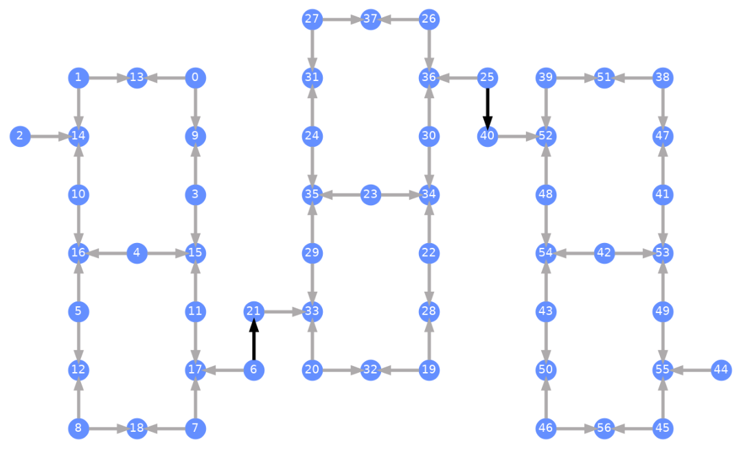
各Qubitにはラベルが付けられており、色付きの矢印が2量子ビットゲートを表しています。灰色の矢印はCZゲートで、黒い矢印はチップ間のCXゲートです(Qubit と を接続しています)。矢印の方向は、これらのゲートが実行されるデフォルトの方向を示しており、各2量子ビットチャネルのデフォルトでどのQubitがコントロール/ターゲットであるかを指定しています。
カスタムBackendに対するトランスパイル
独自のTargetを持つカスタムBackendが定義されたので、このBackendに対して量子回路をトランスパイルすることは簡単です。トランスパイラーパスに必要なすべての関連する制約(基底ゲート、Qubit接続性など)がこの属性に含まれているためです。次の例では、大きなGHZ状態を作成する回路を構築し、上で構築したBackendに対してトランスパイルします。
from qiskit.transpiler import generate_preset_pass_manager

num_qubits = 50
ghz = QuantumCircuit(num_qubits)
ghz.h(range(num_qubits))
ghz.cx(0, range(1, num_qubits))
op_counts = ghz.count_ops()

print("Pre-Transpilation: ")
print(f"CX gates: {op_counts['cx']}")
print(f"H gates: {op_counts['h']}")
print("\n", 30 * "#", "\n")

pm = generate_preset_pass_manager(optimization_level=3, backend=backend)
transpiled_ghz = pm.run(ghz)
op_counts = transpiled_ghz.count_ops()

print("Post-Transpilation: ")
print(f"CZ gates: {op_counts['cz']}")
print(f"ECR gates: {op_counts['ecr']}")
print(f"SX gates: {op_counts['sx']}")
print(f"RZ gates: {op_counts['rz']}")
Pre-Transpilation:
CX gates: 49
H gates: 50

 ##############################
Post-Transpilation:
CZ gates: 146
ECR gates: 6
SX gates: 302
RZ gates: 250
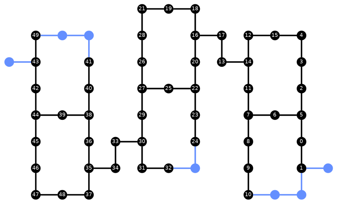
トランスパイルされた回路には、BackendのTargetで基底ゲートとして指定したCZゲートとECRゲートの混合が含まれています。また、レイアウト選択後にSWAP命令を挿入する必要があるため、開始時よりもかなり多くのゲートが含まれています。以下では、plot_circuit_layout()可視化ツールを使用して、この回路で使用されたQubitと2量子ビットチャネルを指定します。
from qiskit.visualization import plot_circuit_layout

plot_circuit_layout(
    transpiled_ghz, backend, qubit_coordinates=total_qubit_coordinates
)
ユニークなBackendの作成
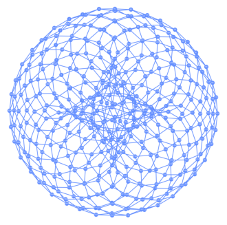
rustworkxパッケージには、さまざまなグラフの大規模なライブラリが含まれており、カスタムグラフの作成が可能です。以下の視覚的に興味深いコードは、トーリックコードにインスパイアされたBackendを作成します。その後、Backendの可視化セクションの関数を使用してBackendを可視化できます。
class FakeTorusBackend(BackendV2):
    """Fake multi chip backend."""

    def __init__(self):
        """Instantiate a new backend that is inspired by a toric code"""
        super().__init__(name="Fake LOCC backend")
        graph = rx.generators.directed_grid_graph(20, 20)
        for column in range(20):
            graph.add_edge(column, 19 * 20 + column, None)
        for row in range(20):
            graph.add_edge(row * 20, row * 20 + 19, None)
        num_qubits = len(graph)
        rng = np.random.default_rng(seed=12345678942)
        rz_props = {}
        x_props = {}
        sx_props = {}
        measure_props = {}
        delay_props = {}
        self._target = Target("Fake Kookaburra", num_qubits=num_qubits)
        # Add 1q gates. Globally use virtual rz, x, sx, and measure
        for i in range(num_qubits):
            qarg = (i,)
            rz_props[qarg] = InstructionProperties(error=0.0, duration=0.0)
            x_props[qarg] = InstructionProperties(
                error=rng.uniform(1e-6, 1e-4),
                duration=rng.uniform(1e-8, 9e-7),
            )
            sx_props[qarg] = InstructionProperties(
                error=rng.uniform(1e-6, 1e-4),
                duration=rng.uniform(1e-8, 9e-7),
            )
            measure_props[qarg] = InstructionProperties(
                error=rng.uniform(1e-3, 1e-1),
                duration=rng.uniform(1e-8, 9e-7),
            )
            delay_props[qarg] = None
        self._target.add_instruction(XGate(), x_props)
        self._target.add_instruction(SXGate(), sx_props)
        self._target.add_instruction(RZGate(Parameter("theta")), rz_props)
        self._target.add_instruction(Measure(), measure_props)
        self._target.add_instruction(Reset(), measure_props)
        self._target.add_instruction(Delay(Parameter("t")), delay_props)
        cz_props = {}
        for edge in graph.edge_list():
            cz_props[edge] = InstructionProperties(
                error=rng.uniform(7e-4, 5e-3),
                duration=rng.uniform(1e-8, 9e-7),
            )
        self._target.add_instruction(CZGate(), cz_props)

    @property
    def target(self):
        return self._target

    @property
    def max_circuits(self):
        return None

    @classmethod
    def _default_options(cls):
        return Options(shots=1024)

    def run(self, circuit, **kwargs):
        raise NotImplementedError("Lasciate ogne speranza, voi ch'intrate")
backend = FakeTorusBackend()
# We set `figsize` to a smaller size to make the documentation website faster
# to load. Normally, you do not need to set the argument.
plot_gate_map(backend, figsize=(4, 4))
num_qubits = int(backend.num_qubits / 2)
full_device_bv = QuantumCircuit(num_qubits, num_qubits - 1)
full_device_bv.x(num_qubits - 1)
full_device_bv.h(range(num_qubits))
full_device_bv.cx(range(num_qubits - 1), num_qubits - 1)
full_device_bv.h(range(num_qubits))
full_device_bv.measure(range(num_qubits - 1), range(num_qubits - 1))
tqc = transpile(full_device_bv, backend, optimization_level=3)
op_counts = tqc.count_ops()
print(f"CZ gates: {op_counts['cz']}")
print(f"X gates: {op_counts['x']}")
print(f"SX gates: {op_counts['sx']}")
print(f"RZ gates: {op_counts['rz']}")
CZ gates: 834
X gates: 18
SX gates: 1534
RZ gates: 1150